Depending on how the electrical components are arranged in the circuit, we can determine their properties and combine them into equivalent elements, such as total resistance or capacitance.
Circuits
- Definition: closed loop or path that allows electrical current to flow from a power source, through components, and back to the source.
In a circuit, we can classify the components into different categories.
By their functions:
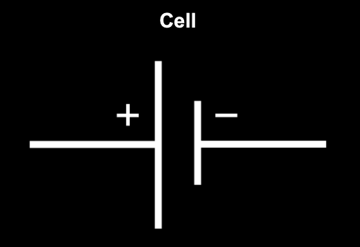
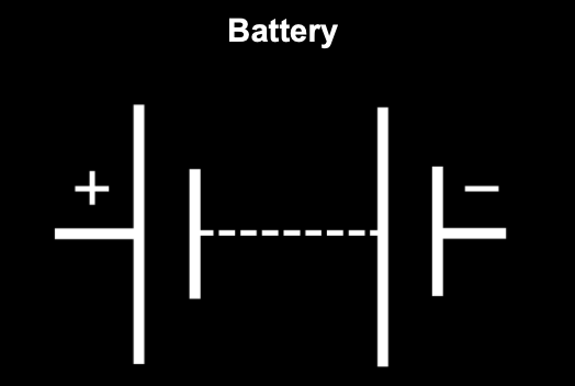
Generators
They supply energy to the circuit by creating a difference of potential.
 |
 |
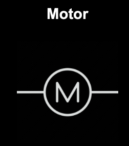
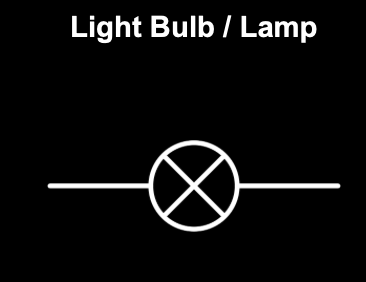
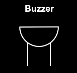
Receivers
They transform the electric energy to generate motion, light, sound, or heat.
 |
 |
 |
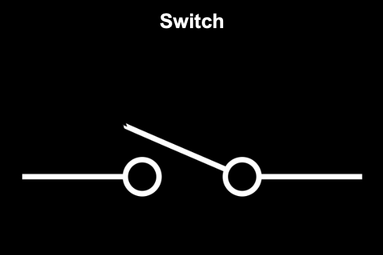
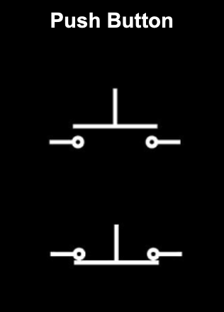
Control and protection elements
They control the flow of electricity or protect the circuit. Some are:
 |
 |
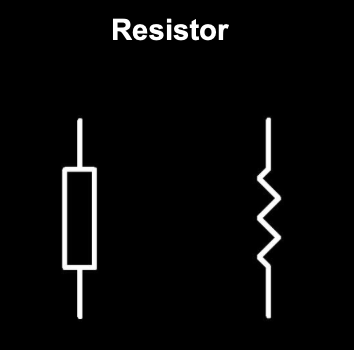
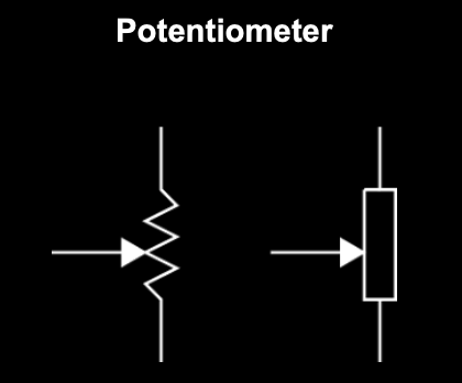
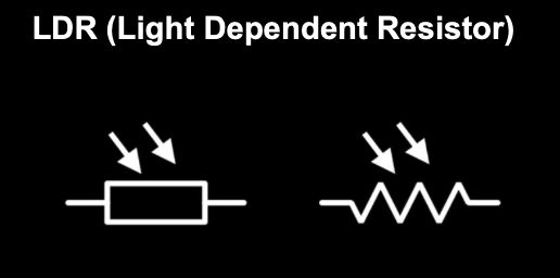
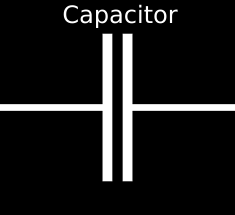
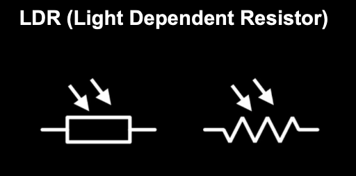
Passive electronic components
They can only receive energy, which it can either dissipate, absorb, or store in an electric field or a magnetic field.
 |
 |
 |
 |
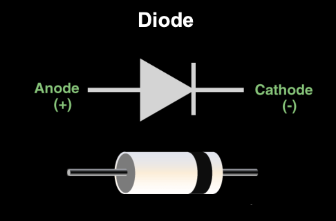
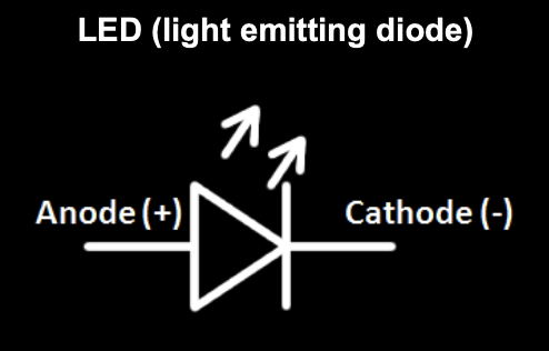
Active electronic components
They control the flow of current and, or amplify signals.
 |
 |
 |
Circuits in series
Components are connected end to end, creating a single path for current to flow through.
Properties:
- Same path, which means that the circuit is disrupted if one part fails.
- Same current / intensity in all elements
- Voltage “distributed” across all the components
Batteries
When batteries are connected in series and the positive terminal of one battery connects to the negative terminal of the next, the voltages of all the batteries add together. But when batteries are connected in opposition, the positive terminal of one battery is connected to the positive terminal of the other, or the negative to negative, effectively reversing one battery relative to the other, the voltages subtract.
\(V_{eq} = V_1 \; \pm \; V_2 \; \pm \; ... \; \pm \; V_n\)
Resistances
When resistors are connected in series, the same current flows through each of them. In this arrangement, the total or equivalent resistance is simply the sum of the individual resistances.
\(R_{eq} = R_1 + R_2 \; + \; ... \; + \; R_n\)
Circuits in parallel
Current flows through multiple paths, creating branches.
Properties:
- Multiple current paths, which summed should be equal to the total intensity of the circuit.
- Constant voltage, equal to the one of the source.
- Independent operation of the components
Batteries
When batteries of the same voltage are connected in parallel, the total voltage equals the value of one.
\(V_{eq} = V_1 = V_2 = ... = V_n\)
Resistances
When resistors are connected in parallel, they’re all under the same voltage and the inverse of the equivalent resistance equals the sum of the inverses of the individual resistances:
\(\frac{1}{R_{eq}} = \frac{1}{R_1} + \frac{1}{R_2} + ... + \frac{1}{R_n}\)
Tips
- It’s important to note that in a same branch, there can be components in series. In these cases, find the equivalent resistance between those two and then find the equivalent resistance of the whole circuit.
- To find the intensity or voltage in all the components, don’t forget to apply the properties mentioned before and ohm’s law in each component and in the entire circuit (with the equivalent resistance, voltage, and intensity).
- Current will always prefer going through the easier path (with less resistance).
Measuring Instruments
This is something we must apply to understand how the different devices that we use to measure electrical parameters work:
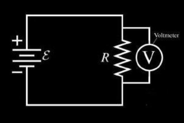
Voltmeter
Voltmeters are used to measure voltage at a certain point, therefore they’re connected in parallel. To assure that it doesn’t affect the rest of the circuit, they have an elevated internal resistance. This way, minimal current flows through the branch.
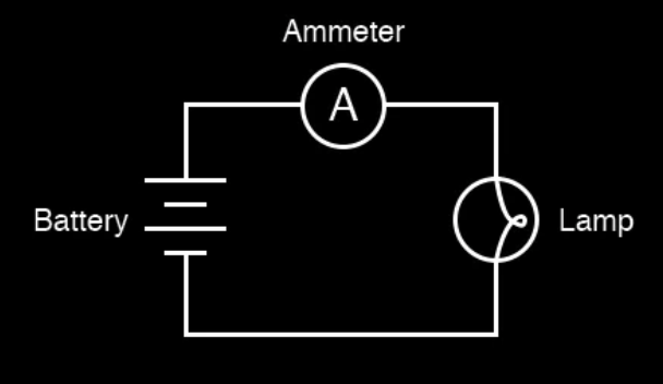
Ammeter
Ammeters are used to measure the intensity flowing at a certain point, hence they’re connected in series. In order to avoid an affection to the circuit, they have a really low resistance.
Written by Sofia Osorio